ROSS MICROSCOPE
c. 1873
SIGNED: ROSS, London, 3727
SERIAL NUMBER: 3727
MODEL: LARGE
or LARGE FIRST
CLASS
or T. ROSS 1861 EXHIBITION-MODEL MICROSCOPE
AUTHORS: Barry Sobel and Jurriaan de Groot
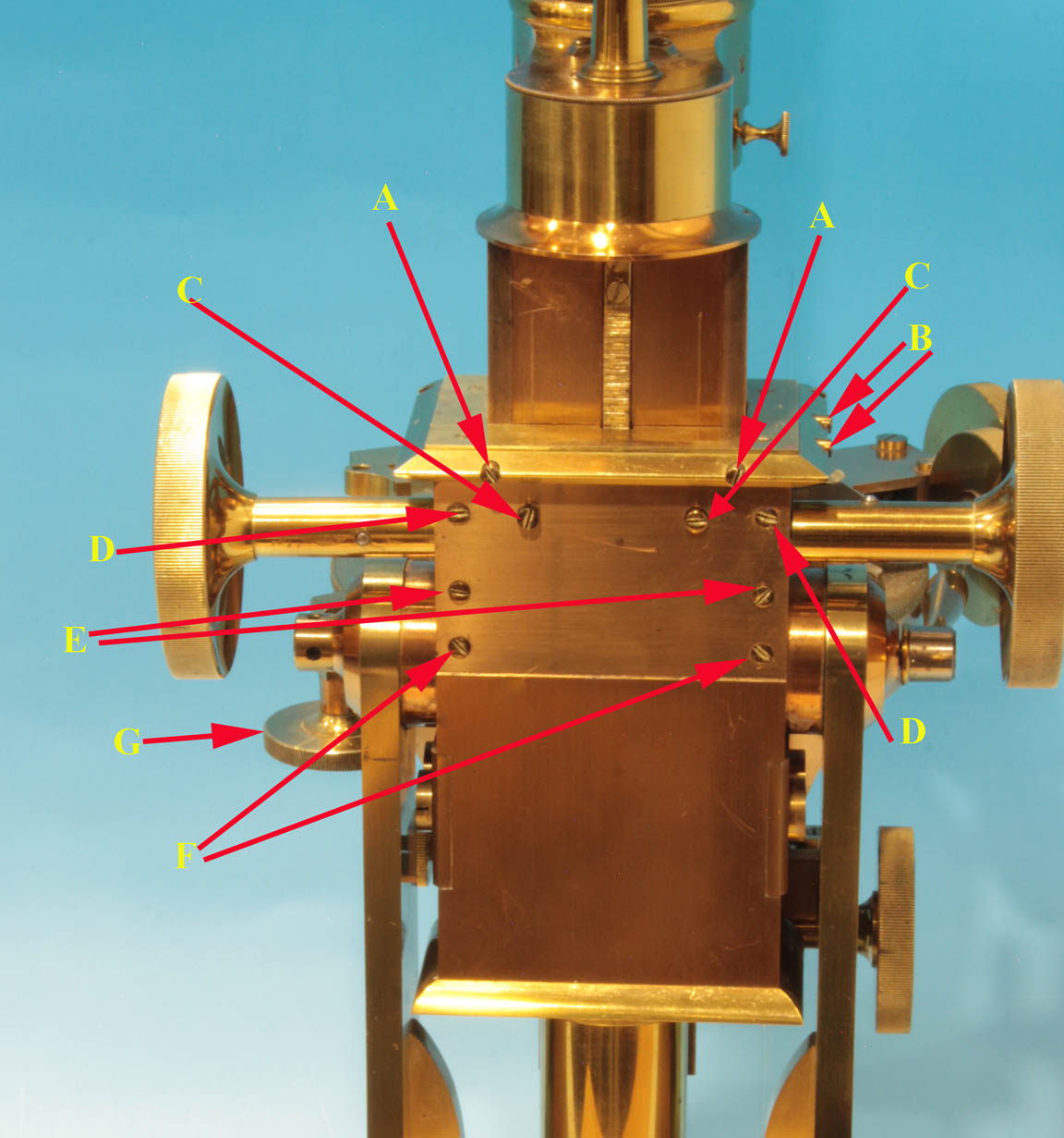
This page shows the screws used for adjusting the tension and fit for the bar and also for the rack and pinion. A and B adjust the fit of the bar itself in the back and forth and right-left directions respectively. They put pressure on the bar in the corners where it registers against parts of the plate they screw against. The remainder of the screws adjust the fitting of the rack and pinion and adjust the tension on the axle carrying the pinion. This is a push-pull system with screws to push the plate away from the bar, or pull it towards it.
C are screws that push the limb forward, away from the back of the limb housing, carrying the pinion away from the rack
D are the screws that hold the top of the plate to the housing for the bar, and in addition as tightened, also increase tension on the axle holding the pinion.
E are a second set ofscrews that push the plate away from the barF are the screws that hold the bottom of the plate to the housing for the barG is the knob which rotates the stage
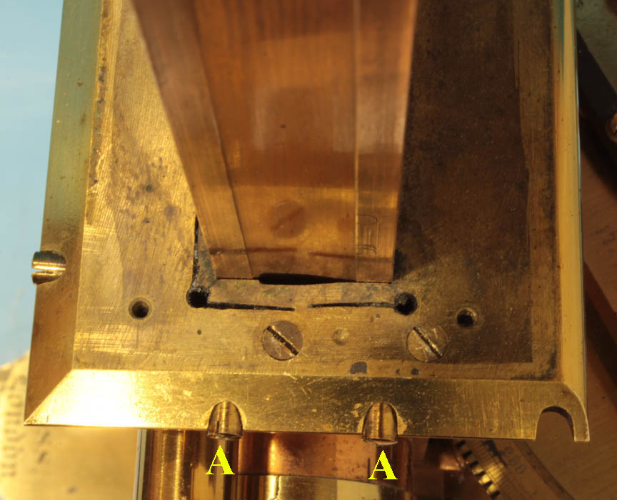
The system by which the screws at
A
act on the brass housing for the bar are shown below. The top plate of the housing has slots cut so that the screws contact these bendable areas which register against the raised brass corners of the limb. The thin brass cover over this top plate has been removed for clarity.
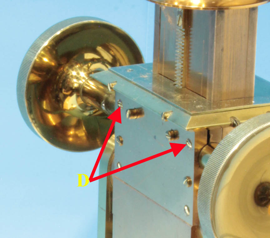
The image here to the left shows the D
screws from another perspective illustrating how slots in the back plate of the housing allows the screws to increase tension on the axel which has the pinion.