ANTIQUE MICROSCOPES AND OTHER ANTIQUE SCIENTIFIC INSTRUMENTS
MICROSCOPE-ANTIQUES.COM © 2013-2024
CONDENSERS AND RELATED SUBSTAGE DEVICES

| HISTORY OF SUBSTAGE ILLUMINATION | A PARTIAL LIST OF CONDENSERS |
INTRODUCTION:
Since the time of the first microscopes, it was recognized that a good source of light to illuminate the object being studied was essential. At first this was light from above the object (which was usually opaque). This top illumination is reviewed elsewhere on this site. On this page we are concerned with illumination of translucent or transparent objects from below the stage.
Soon after this type of object became a popular subject, methods to assure bright and regulated illumination were required. At first, as in the case of Van Leeuwenhoek, the bottom of the microscope was simply aimed at a suitable light source. This type of lighting sufficed for some low power applications, but as the optics and resolution of the microscope improved, this type of lighting became more and more unsatisfactory.
HISTORY OF SUBSTAGE ILLUMINATION:
In time, various methods to improve substage illumination were devised in ever-increasing degrees of sophistication. The first attempt at a more convenient source of substage lighting was that of Hertel about 1715, when he was the first to apply a substage mirror to the microscope. This made direction of light more convenient, but did nothing to reduce extraneous beams of light causing glare and other aberrations and did not by itself concentrate the light upon the object being studied.
In 1727 Edmund Culpeper was the first to use a concave substage mirror to concentrate light on an object with less extraneous light and glare, depending on how the mirror was positioned. This was an improvement for low power work, but as the higher power objectives have a smaller field of view, it became necessary to reduce the diameter of the light source so that the object was illuminated, but extraneous rays were reduced. Extraneous rays could produce double images, unwanted shadows and other effects which could result in misinterpretation of the structures being studied. Another aberration introduced into the illumination by the mirror is that although much of the light was reflected by the mirror surface of the back of the mirror, the glass in front of that surface could also reflect light at a different angle, causing some blurring of the edges of details, especially at high power. Although an ordinary triangular prism could be used instead of a mirror to obviate the secondary reflection, it did not concentrate the light and projected a wide beam.
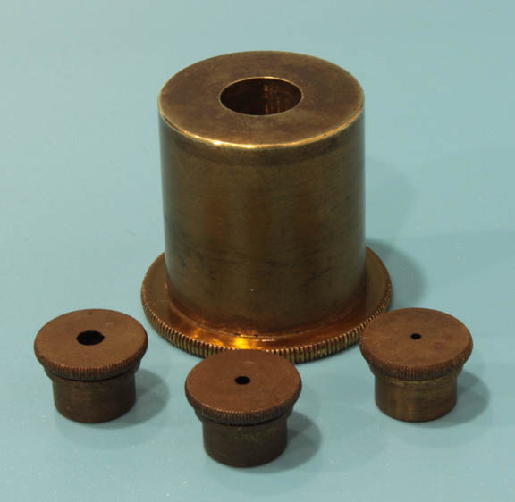
The next logical step was to provide some method of stopping down the light source so as to illuminate most of the field of view, but no more than that. This was provided by a variety of devices, the simplest of which was a pinhole cylinder stop, different diameter holes being available from a variety of stops as the user exchanged one for another. Although a simple method, it is quite inconvenient to change one for another. To change stops usually required the housing for the stop to be removed or, alternatively, in some cases, the slide removed from the stage. This type of simple little cylindrical stop fitting was supplied with German student microscopes as late as 1939 and in later years fit into the same substage fittings which could alternatively accept an Abbe condenser(see below) instead of just a pinhole diaphragm. This type of stop had an advantage of being able to be brought close to the slide, providing better control of the size of the cone of light illuminating the specimen.
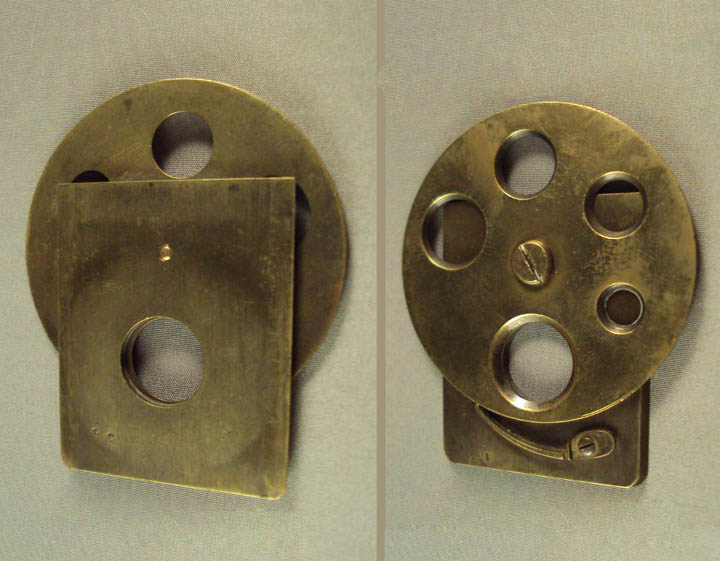
A more convenient method is a wheel of apertures, a disk with different size openings that can be easily rotated to change the size of the aperture. This accessory could slide into a slot built in to the bottom of the stage as shown to the left, or later, as shown to the right, mounted on a cylinder which fit inside a ring on the bottom of the stage, or into a substage fitting. In addition, in some cases, the wheel of apertures was directly affixed to the bottom of the stage as in the medium sized Busch microscope on this site, or was even integrated into the stage so that the apertures were close to the top of the stage. In the Acme No 4 Physicians microscope, the wheel was attached to the bottom of the stage but could be swung completely out of the optical axis on its support.
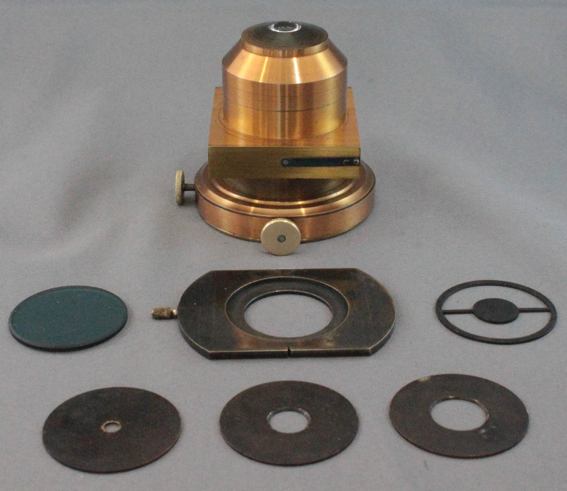
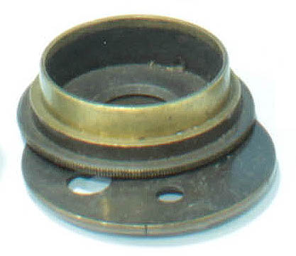
As lenses became part of condensers, provisions were made to accept little discs or plates at the bottom of the condenser. An example of Bausch and Lomb's Condenser with a slide that can accept any number of aperture stops is shown to the left.

An alternative, developed a bit later, still used today, was to have a swing-out or a pull-out holder under lensed condensers, fitting into which were various size plates of apertures (or oblique or darkfield stops or color filters).
Later, a variable opening such as an iris diaphragm, provided a continuous range of openings. The iris diaphragm was first patented in the United States in 1858 as an accessory for cameras. Apparently J.H. Brown was the first to design the present form of iris diaphragm for use with the substage of the microscope, about 1867 as described that year in the Transactions of the Microscopical Society, XV, p 74. The iris eventually became an integral part of the illumination apparatus of virtually all major compound microscopes, even to this day, though cheap microscopes may have no diaphragm, the old fashioned wheel of apertures, or even no means of aperture adjustment at all. Higher quality microscopes now have two substage iris diaphragms, one close to the optics of the condenser known as the aperture diaphragm and another below, known as the field diaphragm. The use of these is discussed below under Kohler Illumination.
The next step in the development of substage illumination was the use of lenses under the stage which served as condensers of the light. Initially, these were simple lenses. With a simple lens and relatively low magnification, a wide light source will provide a fairly good illumination without obvious severe aberrations. A narrow light source will worsen the abberations however. For this reason, diffusing glasses between the lens of the condenser and the specimen or wider sources of illuminations like the white cloud illuminator
below the lens of the condenser were used to widen the incomming cone of light and make it appear more uniform. The white cloud illuminator was invented and produced by Cornelius Varley starting in the 1820s.
A concave mirror or white cloud illuminator sufficed for transmitted light studies using lower power objectives up to 10X power. As the numerical aperture of objectives increased however, a lensed condenser became more important to allow the microscopist to take advantage of the full numerical aperture of these objectives.
Despite the development of lensed condensers long before, as documented below, it was not until after 1880 that the use of condensers became routine. This occurred at that time due to the rise of the importance of bacteriology which required higher power objectives with higher resolution and therefore also required substage condensers in order to make maximal use of their improved numerical aperture.
Among the earliest well-known complete English condensers was the Gillett condenser, first proposed by Gillett in the 1840s, and popularized by Ross, who produced most of them, starting about 1850. It featured a colotte wheel of stops and openings of various sizes and types. In the example shown here to the left, its first version, it had a correction collar to correct for aberrations produced by the slide above it. This was useful at the time because it simply clamped below the stage or onto a tail piece and fine adjustments in focus were difficult to do with such an arrangement. Furthermore, slide thicknesses were quite variable in the mid-19th century, making the condenser correction collar more important. This feature was quickly abandoned however as soon as good substage focusing mechanisms and standardized slide thickness became common.
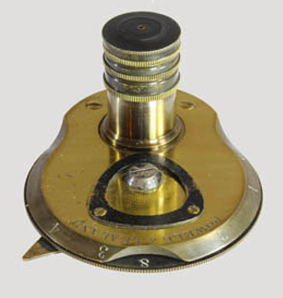
 As early as 1841, Powell and Lealand were producing an achromatic condenser(left), which they continued to supply with their prototypical New Microscope of 1843 and in 1857 they introduced their High Power Achromatic Condenser (right), which was also aplanatic over most of the field, and could be used for lower powers by removing the top element. This condenser, shown to the right, continued to be recommended by many experts as one of the best for half a century or more.
In 1865 Webster's Universal(WU) condenser, was described in Science Gossip of that year and this condenser and variations of it rapidly became the most common type both in England and the United States. In fact, many authors call any condenser with a disk wheel of apertures a Webster
, though strictly speaking they are often not. The original Webster condenser consisted of a simple achromatic doublet beneath a single planoconvex projecting lens. The original WU condenser had a wheel of stops. One fully opened, one a dark ground stop, one crescent-shaped opening for oblique illumination and a smaller clear opening with a disk that could swing over this opening covering it, but with a still smaller central aperture. A variant of this condenser was a wheel of apertures above which was a RMS fitting to accept an achromatic objective as the optics. Variations in this condenser were quite common.
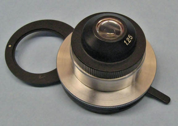 By 1873 the famous German expert optician Ernst Abbe had devised his famous illuminator which is still used today. It has a large thick planoconvex top element over a thinner planoconvex element for low power work and a third removeable top lens for oil immersion. It is not corrected for chromatic or spherical aberration, but has a very high numerical aperture. It therefore produces a wide cone of concentrated light. Since most of the aberration occurs at the edge of this cone, stopping down the aperture to what is needed for the particular obective in use at the time helps to reduce these aberrations. For this reason the non-achromatic and inexpensive Abbe condenser is still widely used even today. When its top element is removed it functions fairly well as a low power condenser. Early forms allowed the top element to be unscrewed or simply pulled off; later versions had the top element on a fitting that swung it in or out of the optical axis. The image to the left is a typical Abbe condenser from the mid-twentieth century and later. On its bottom it has an iris diaphragm and a swing-out ring below that to hold stops for darkfield, Rheinberg, or oblique illumination. For critical work at higher powers, even today, the Abbe is inferior to an achromatic/aplanatic condenser. It is still an excellent condenser at low power for dark field work with a central stop or for Rheinberg illumination. The three lens Abbe condenser can be used with oil immersion to the bottom of the slide with oil immersion objectives oiled to the top of the slide.
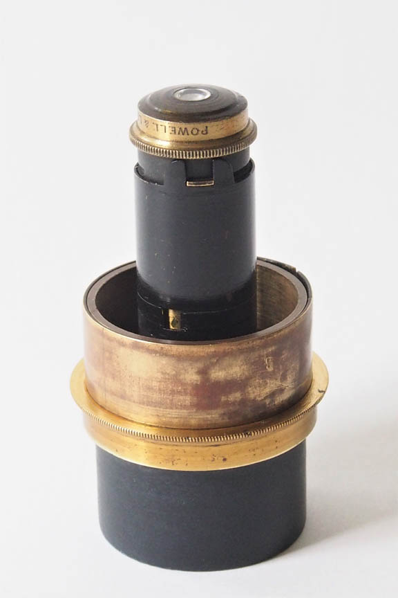
In 1881 Powell & Lealand came out with an oil immersion Abbe-type chromatic condenser suitable for use with higher powers.
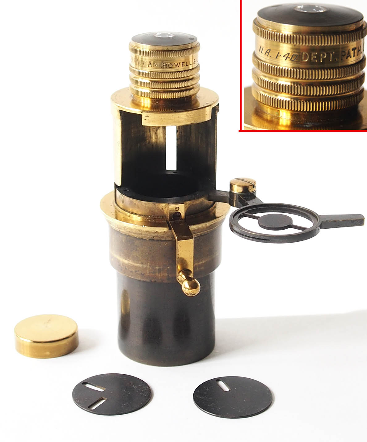 In 1886 Powell & Lealand came out with an achromatic oil immersion condenser with a N.A. of 1.3 and in 1891 an apochromatic version with the same housing. This unusual condenser housing includes a provision to raise and lower a central aperture or stop while the optical portion remains in place, properly focused for optimal illumination. As time went on, the designs of microscopes changed to allow the area at the bottom of the condenser optics to be readily accessible. This was in large part due to thinner mechanical stages. This type of condenser was then no longer needed.
As time went on, and higher power objectives demanded further reductions in the aberration from the light source, condensers which were achromatic, aplanatic, or both were made by English, American, and Continental opticians, although as noted the Abbe condenser remained popular especially on Leitz and Zeiss stands. The addition of a rack and pinion mechanism to move the condenser horizontally out of the optical axis also allowed oblique lighting using this condenser.
Some were equipped with a fitting that included an
Abbe condenser that could swing out of the way, revealing a second condenser holder to accomodate an alternative condenser without the need to completely remove the Abbe.
Specialized condensers or parts were devised for various purposes including oblique illumination, dark ground illumination, and polarized light illumination, all discussed elsewhere. Some condensers were devised to combine all the common types of illumination, the Swift Universal perhaps being the pinnacle of these efforts. Such comprehensive combination condensers are no longer made, most being able to perform one to three functions such as brightfield, Phase contrast and, for low power only, dark ground illumination, with one condenser. This occurred because some optics, like high power dark ground illumination, became too complex to incorporate into a single instrument also designed for other functions, and the addition of more types of microscopy such as phase contrast, interference contrast, fluorescence microscopy, etc. Modern microscopes like the Olympus Vanox offered as many as 9 different condensers, some of which could perform a few different functions, but none could perform more than about 3 or 4, and some only one type.
Among specialized condensers several types were developed. These included those developed for use with very low powers, darkfield (darkground) work, polarized light, oblique lighting, phase contrast, and interference contrast. An example of a condenser for very low powers is the Watson Macroilluminator.
OPTIMAL ADJUSTMENT OF CONDENSERS
Contrast can be defined as the ability to see differences in brightness of different areas of a subject. The greater the difference between the darkest and lightest areas the higher the contrast. Resolution on the other hand is a measure of how small a distance between two features can be and still allow the observer to see the features. This resolving power may not be helpful if the contrast is so low that the different objects all blend in to each other. Adjustment of illumination to achieve the best combination of contrast and resolution for the object being studied is an important task for the microscopist.
As far as condensers are concerned, as the diameter of the cone of light approaches the numerical aperture, the better the resolution. On the other hand, a larger cone of light will reduce contrast. For many applications, a cone of light which is about 15% below the n.a. of the objective is often an optimal mix of contrast and resolution. The size of the cone of light is in most cases dependent on the adjustment of the aperture diaphragm of the condenser, whether by stops or an iris type and can be judged by removing the eyepiece and observing the back focal plane of the objective, either directly, or with the aid of a phase telescope or Bertrand Lens. This is not the only part of the adjustment needed for optimal illumination however.
Besides creating the correct size of the cone of light, that light must be focused properly to achieve even and bright illumination accross the part of the field being studied. This is why the substage has a provision for focusing. The result again may be visualized at the back focal plane of the objective. If properly done, the back field of the objective will be almost filled with light that is bright and of even intensity without any hotspots
, (or at least is of even intensity in the center of the field in the case of critical illumination
). As one peruses the development of various illummination systems, one can appreciate the developing ability to achieve optimal illumination.
ADJUSTING THE LIGHT SOURCE
Other than the empirical method of looking at the back focal plane of the objective, more exact and sophisticated methods of achieving optimal illumination were developed. The two most important are 1)Critical Illumination (also known as Nelsonian Illumination) and 2)Kohler Illumination(1893). In critical illumination, the light source must have a distinct edge to focus on-a filment in a lightbulb or the thin edge of a broad wick in a lamp. With this system, by manipulation of the lightsource itself, the substage mirror and the condenser, the most intense light is focused in the same plane as the object being studied. With Kohler illumination, the light source is focused on the stop or iris in the condenser below the optical portion. The latter allows even clear illumination without a hotspot
in the center of the field and without the image of the filament or lamp wick distracting the observer from the subject. Critical illummination was developed first and requires the ability to adjust the aperture of the condenser only. For Kohler illumination, a second aperture adjustment near the light source is required. This was often added to stand-alone electric illuminators, or later, when the light source was built into the microscope itself, this field diaphragm was built into the base of the microscope. Even today however, cheaper microscopes are not equipped with a field diaphragm.
HOW TO USE A CONCAVE MIRROR FOR ILLUMINATION WITH LOW POWER (10X OR LESS):
1. Use a light source of low to medium intensity.
2. If the light source has adjustments make adjustments to fill the entire mirror with light.
3. If available, a light blue filter and a ground glass filter will optimize the light source
4. If the mirror is adjustable in relation to the stage, place a piece of white paper over the opening of the stage and move the mirror up and down to achieve the smallest patch of light.
5. Place the object on the slide and focus on it
6. Remove the eyepiece and observe the back element of the objective which should be full or nearly full; if the n.a. is 0.25 or higher it will be less than full.
7. Tilt or turn the mirror to center the light in the back lens of the objective.
8. Close the substage diaphragm until it slightly cuts into the back lens.
9. Replace the eyepiece and optimal conditions will now exist.
HOW TO SET UP FOR CRITICAL ILLUMINATION:
1. The condenser must be centered in the field of the objective. This is done with the condenser racked down and the smallest aperture used.
2. A corrected condenser (not an Abbe type) must be used. Achromatic and Aplanatic would be optimal
3. The condenser aperture is then opened and racked up until an image of the light source, either a band in the case of the wick, or an image of the filament from an electric lamp is in focus when the specimen is in focus. A ribbon filament is much preferred to a spiral filament for obvious reasons.
4. Note that if the illumination is not directly through the condenser and a mirror is used, it must be a flat mirror, not concave. Concave mirrors are meant to be used without a condenser.
HOW TO SET UP FOR KOHLER ILLUMINATION:
This is far more simple for a modern microscope with built-in illumination than it is for an antique microscope with external illumination. This is how this is done with a modern microscope with built-in light source and diaphagms:
1. Use a low power objective
2. Focus on the subject
3. Close the FIELD diaphragm to a small opening
4. Use the CONDENSER focus to focus on the leaves of the field diaphragm
5. Center the field diaphragm using the condenser centering controls
6. Confirm the diaphragm is centered by slowly opening it and confirming it approaches the edge of the field equally on all sides
7. Once 6 is completed, open it further, but just enough to cover the whole field-not wide open
8. Adjust the Aperture stop to fill 75 to 85% of the field
9. NOTE: the aperture stop and field stop will need adjustment with each objective.
NOTE: The above assumes the lamp is already at the optimal distance from the condenser. In some cases this may need to adjusted and the lightbulb may need to be centered as well.
The filament will need to be in the center of the field.
In cases where the distance of the light source is variable, the setup may be a bit different as the light filament should be focused on the leaves of the aperture diaphragm.
KOHLER ILLUMINATION USING AN ANTIQUE MICROSCOPE:
1. Set the substage condenser height so the top lens is nearly touching the slide.
2. Place the front of the stand-alone microscope illuminator about 6 inches from the substage mirror.
3. Use the focusing controls on the lamp to focus a sharp image of the lamp filament on the underside of the closed aperture diaphragm (using a mirror to visualize this).
4. Place a specimen on the stage, and open the aperture diaphragm.
5. Focus the microscope on the specimen.
6. Close the field diaphragm on the lamp and focus the microscope Condenser to visualize a sharp image of the field diaphragm superimposed on the specimen.
7. By adjusting the lamp and flat side of the mirror, move the field iris image to the center of the field.
8. Slowly close the aperture diaphragm of the condenser until there is a slight reduction in brightness-this should improve contrast.
9. With higher power objectives, the field iris will need to closed down and the aperture iris opened more
10. One can check the setup by removing the eyepiece and observing the sharply focused filament in the back focal plane of the objective, with or without a phase telescope or Bertrand lens.
11. The aperture diaphragm closed to 75 to 85% of the field usually results in reduction of glare and increased contrast.
CONTRAST VS RESOLUTION:
Some specimens have a refractive index close to water. These specimens, like fresh squamous cells from the inside of one's cheek are an example. All the resolution on earth will not allow good visualization of such specimens unless contrast is increased. This means closing down the aperture diaphragm, usually sacrificing some resolution. On the other hand, resolution may be critical, as when trying to resolve the individual punctae of difficult diatoms. But in the case of diatoms, which have a refractive index close to the mounting media, contrast is also important. This problem can be solved, to a great extent, using oblique illumination. Oblique illumination provides more contrast without sacrificing as much resolution. This is how microscopists of the 19th century were able to resolve difficult objects.
In modern times though, other techniques of increasing contrast have been developed. These include sophisticated darkfield condensers, phase contrast microscopy and interference contrast microscopy, each requiring its own type of condenser and additional optical components. Another method is to use a mountant with a very high refractive index which will also increase contrast.
PARTIAL
LIST OF SUBSTAGE ILLUMINATORS AND CONDENSERS(DATES APPLY TO THE ACTUAL ACCESSORY PICTURED, NOT NECCESARILY THE DATE OF EARLIEST USE.
PLEASE CLICK ON THE IMAGES FOR MORE INFORMATION, WHERE AVAILABLE
OPTIMAL ADJUSTMENT OF CONDENSERS
Contrast can be defined as the ability to see differences in brightness of different areas of a subject. The greater the difference between the darkest and lightest areas the higher the contrast. Resolution on the other hand is a measure of how small a distance between two features can be and still allow the observer to see the features. This resolving power may not be helpful if the contrast is so low that the different objects all blend in to each other. Adjustment of illumination to achieve the best combination of contrast and resolution for the object being studied is an important task for the microscopist.
hotspots, (or at least is of even intensity in the center of the field in the case of
critical illumination). As one peruses the development of various illummination systems, one can appreciate the developing ability to achieve optimal illumination.
Other than the empirical method of looking at the back focal plane of the objective, more exact and sophisticated methods of achieving optimal illumination were developed. The two most important are 1)Critical Illumination (also known as Nelsonian Illumination) and 2)Kohler Illumination(1893). In critical illumination, the light source must have a distinct edge to focus on-a filment in a lightbulb or the thin edge of a broad wick in a lamp. With this system, by manipulation of the lightsource itself, the substage mirror and the condenser, the most intense light is focused in the same plane as the object being studied. With Kohler illumination, the light source is focused on the stop or iris in the condenser below the optical portion. The latter allows even clear illumination without a
hotspotin the center of the field and without the image of the filament or lamp wick distracting the observer from the subject. Critical illummination was developed first and requires the ability to adjust the aperture of the condenser only. For Kohler illumination, a second aperture adjustment near the light source is required. This was often added to stand-alone electric illuminators, or later, when the light source was built into the microscope itself, this field diaphragm was built into the base of the microscope. Even today however, cheaper microscopes are not equipped with a field diaphragm.
1. Use a light source of low to medium intensity.
2. If the light source has adjustments make adjustments to fill the entire mirror with light. 3. If available, a light blue filter and a ground glass filter will optimize the light source 4. If the mirror is adjustable in relation to the stage, place a piece of white paper over the opening of the stage and move the mirror up and down to achieve the smallest patch of light. 5. Place the object on the slide and focus on it 6. Remove the eyepiece and observe the back element of the objective which should be full or nearly full; if the n.a. is 0.25 or higher it will be less than full. 7. Tilt or turn the mirror to center the light in the back lens of the objective. 8. Close the substage diaphragm until it slightly cuts into the back lens. 9. Replace the eyepiece and optimal conditions will now exist.
1. The condenser must be centered in the field of the objective. This is done with the condenser racked down and the smallest aperture used.
2. A corrected condenser (not an Abbe type) must be used. Achromatic and Aplanatic would be optimal
3. The condenser aperture is then opened and racked up until an image of the light source, either a band in the case of the wick, or an image of the filament from an electric lamp is in focus when the specimen is in focus. A ribbon filament is much preferred to a spiral filament for obvious reasons.
4. Note that if the illumination is not directly through the condenser and a mirror is used, it must be a flat mirror, not concave. Concave mirrors are meant to be used without a condenser.
This is far more simple for a modern microscope with built-in illumination than it is for an antique microscope with external illumination. This is how this is done with a modern microscope with built-in light source and diaphagms:
1. Use a low power objective
2. Focus on the subject
3. Close the FIELD diaphragm to a small opening
4. Use the CONDENSER focus to focus on the leaves of the field diaphragm
5. Center the field diaphragm using the condenser centering controls
6. Confirm the diaphragm is centered by slowly opening it and confirming it approaches the edge of the field equally on all sides
7. Once 6 is completed, open it further, but just enough to cover the whole field-not wide open
8. Adjust the Aperture stop to fill 75 to 85% of the field
9. NOTE: the aperture stop and field stop will need adjustment with each objective.
NOTE: The above assumes the lamp is already at the optimal distance from the condenser. In some cases this may need to adjusted and the lightbulb may need to be centered as well. The filament will need to be in the center of the field. In cases where the distance of the light source is variable, the setup may be a bit different as the light filament should be focused on the leaves of the aperture diaphragm.
1. Set the substage condenser height so the top lens is nearly touching the slide.
2. Place the front of the stand-alone microscope illuminator about 6 inches from the substage mirror.
3. Use the focusing controls on the lamp to focus a sharp image of the lamp filament on the underside of the closed aperture diaphragm (using a mirror to visualize this).
4. Place a specimen on the stage, and open the aperture diaphragm.
5. Focus the microscope on the specimen.
6. Close the field diaphragm on the lamp and focus the microscope Condenser to visualize a sharp image of the field diaphragm superimposed on the specimen.
7. By adjusting the lamp and flat side of the mirror, move the field iris image to the center of the field.
8. Slowly close the aperture diaphragm of the condenser until there is a slight reduction in brightness-this should improve contrast.
9. With higher power objectives, the field iris will need to closed down and the aperture iris opened more 10. One can check the setup by removing the eyepiece and observing the sharply focused filament in the back focal plane of the objective, with or without a phase telescope or Bertrand lens.
11. The aperture diaphragm closed to 75 to 85% of the field usually results in reduction of glare and increased contrast.
Some specimens have a refractive index close to water. These specimens, like fresh squamous cells from the inside of one's cheek are an example. All the resolution on earth will not allow good visualization of such specimens unless contrast is increased. This means closing down the aperture diaphragm, usually sacrificing some resolution. On the other hand, resolution may be critical, as when trying to resolve the individual punctae of difficult diatoms. But in the case of diatoms, which have a refractive index close to the mounting media, contrast is also important. This problem can be solved, to a great extent, using oblique illumination. Oblique illumination provides more contrast without sacrificing as much resolution. This is how microscopists of the 19th century were able to resolve difficult objects.
PLEASE CLICK ON THE IMAGES FOR MORE INFORMATION, WHERE AVAILABLE
| APPROXIMATE DATE |
NAME | IMAGE | NOTES |
|---|---|---|---|
| c.1715 | FLAT SUBSTAGE MIRROR | 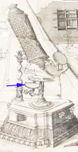 | Hertel was the first to use a (flat) substage mirror for transmitted light microscopy. |
| c. 1727 | CONCAVE CONCAVE SUBSTAGE MIRROR |  | The idea of a concave substage mirror to provide a more concentrated light source was devised by Edmund Culpeper |
| c. 1820s | WHITE CLOUD ILLUMINATOR |
 | Invented by Cornelius Varley, the White Cloud Illuminator provided bright and uniform white light from the sun by using plaster of Paris as a reflector; a bullseye lens concentrated the light. |
| c. 1840 | WHEEL OF APERTURES |  | Also one of the earliest methods of regulating the diameter of the light source |
| c.1841-1850s | Under-the-stage Achromatic Condenser with integral focusing | | This condenser, which Powell & Lealand were making from no later than 1841, was supplied with the original 1843 Powell & Lealand New Microscopewhich was to become the prototype for the famous microscopes of P & L for the next 60 years. |
| c.1850 | GILLETT CONDENSER (first form) |  | An early Gillett condenser by Andrew Ross |
| c. 1865 onward | WEBSTER CONDENSER |  | The Webster condenser was a relatively inexpensive condenser with a plano convex lens above an achromatic doublet, with a wheel of apertures below. The apertures in the wheel changed over time. |
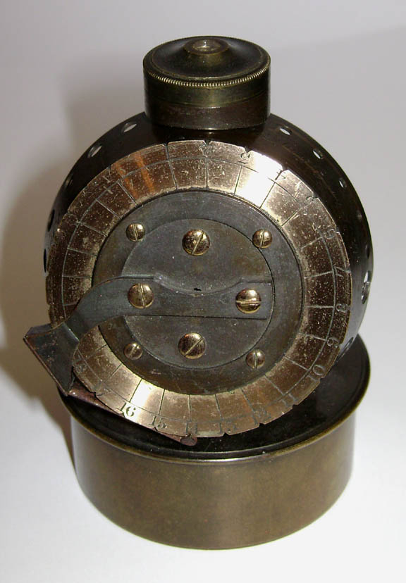
| c. 1865 | SMITH & BECK ACHROMATIC WEBSTER-TYPE CONDENSER | 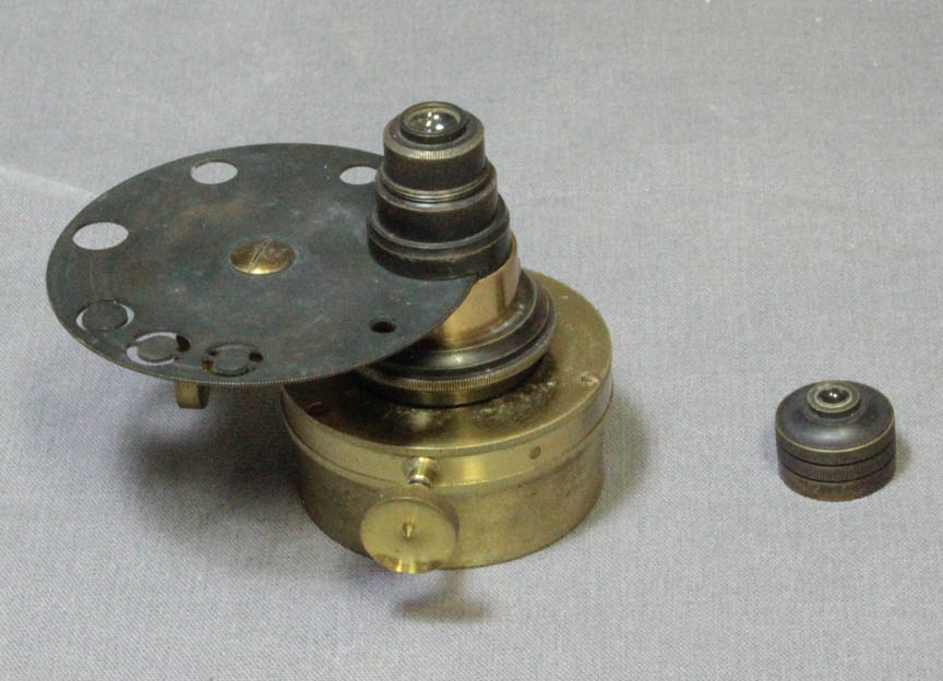 | This is a Webster-type condenser by Smith & Beck with removable front, wheel of apertures, and self-contained centering mechanism. |
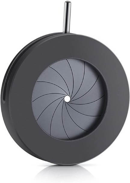
| c. since 1867 | VARIABLE IRIS DIAPHRAGMS | | Iris diaphragms were used to regulate the aperture for light since 1867 and, although uncommonly used until the last years of the 19th century, were in common use by the early 20th century, and are still in use today for this purpose. |
| c.1868 | Hall Universal Condenser by Swift | 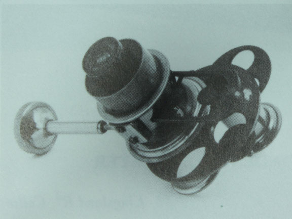 | The first version of the Swift Universal Achromatic Tinted Condenserwas based on Hall's original design of 1868. |
| c.1880 | Abbe Condenser by Queen |  | This Abbe-type of condenser contains a drop-in blue tint filter. Aperture stop caps fit over the top of the condenser. |
| c.1870-1910 | Hall Universal Condenser by Swift | 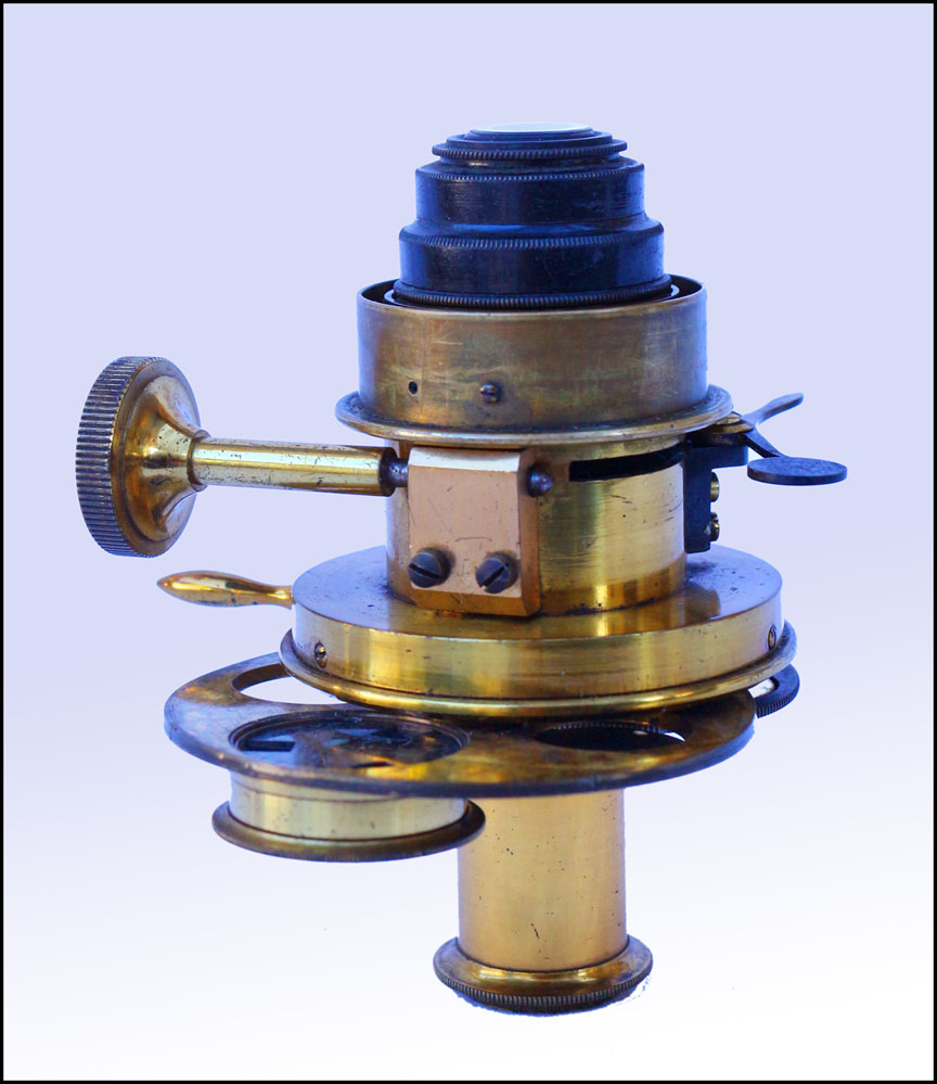 | The second version of the Swift Universal Achromatic Tinted Condenserwas very similar to the first other than a different mechanism to introduce the dark ground stops. |
| c.1870 | ZENTMEYER'S VARIABLE DIAPHRAGM |  | A simple but ingenious form of variable diaphragm invented by Zentmayer. These are quite uncommon |
| c.1870-1910 | Swift Universal Condenser | 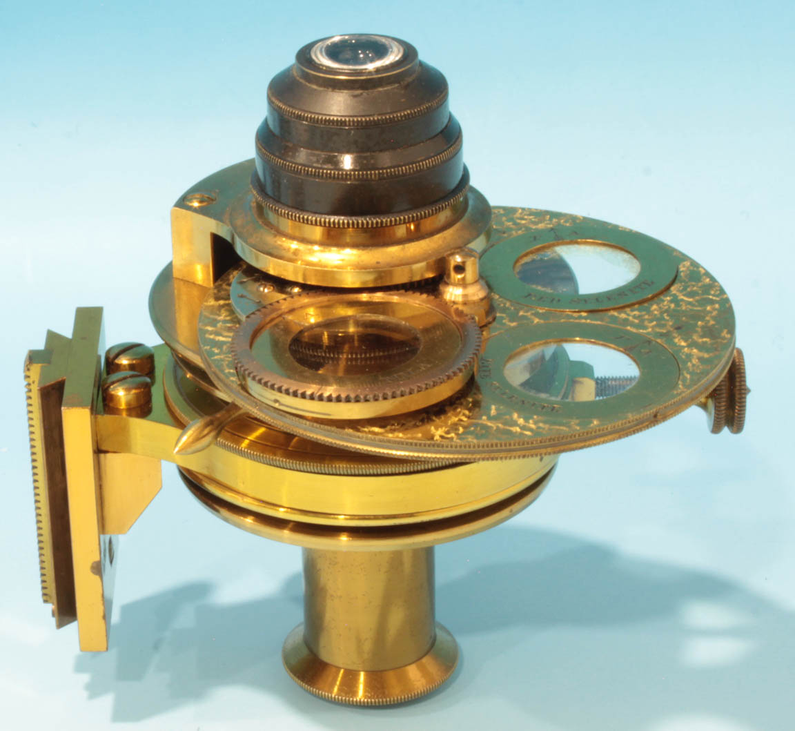 | The newer Swift Universal Condenserwas very similar to the two noted above but was designed to fit in a focusing substage, therefore it had no integrated focusing. At the same time, an additional frame for inserts was added above the lower larger one, designed to carry selenites. |
| c. 1877 | Wale Variable Diaphragm | 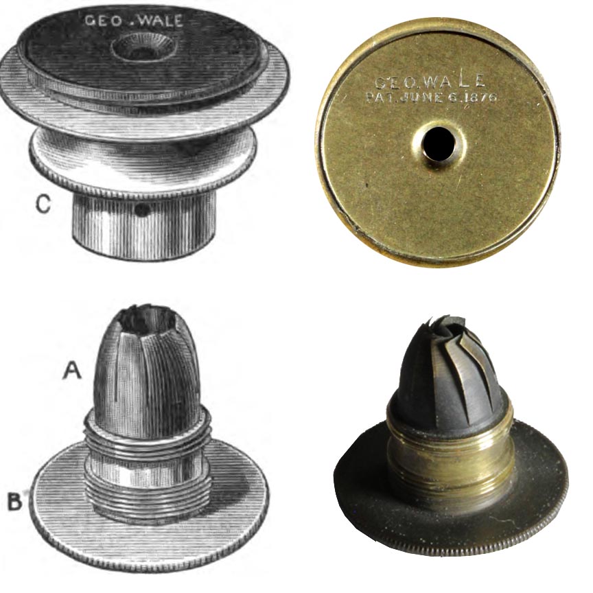 | George Wale patented this variable diaphragm which was simpler to make and assemble than the usual iris type, though it does not work as smoothly or have the same range of aperture size. It is only found on Wale microscopes which were no longer made after 1880 when Wale sold his business to Bausch & Lomb. |
| c.1870s | Ross Improved Gillett Condenser | 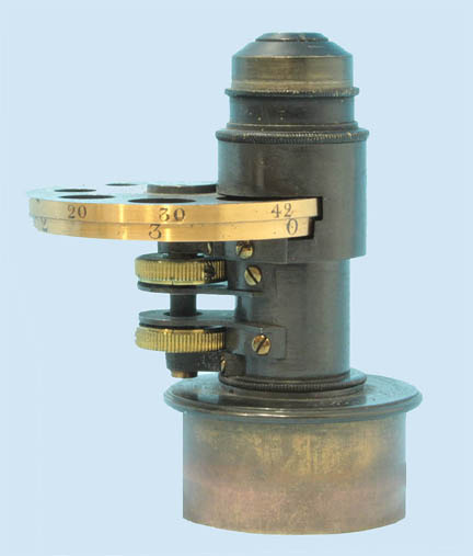 | This condenser is an improvement over the older from of Gillett condenser in that there are two separate wheels, one of different size openings, the other with different diameter stops including darkfield stops and oblique illumination stops. This arrangement allows separate control of stops and apertures, allowing more flexible choices for illumination. |
| c. 1880 | PINHOLE CYLINDER PINHOLE APERTURES |
| One of the earliest methods to regulate the aperture of the light source. Although this example is from about 1880, it was used for many years before and after this. This type of stop had an advantage of being able to be brought close to the slide, providing better control of the size of the cone of light illuminating the specimen, which is why it was still made well into the 20th century. |
| c. 1896- | WATSON PARACHROMATIC CONDENSER |
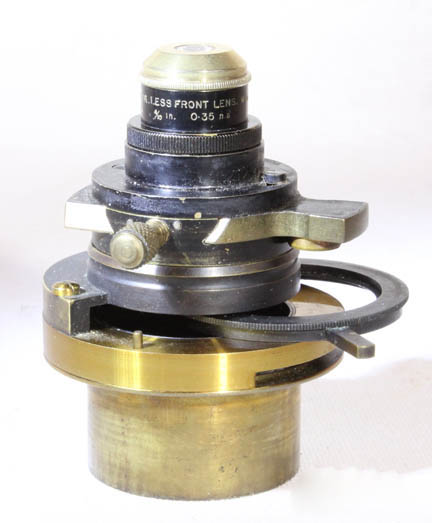 | The Watson Parachromatic Condenser with a n.a. of 1.0 was manufactured starting about 1896. |
| c. 1898- | WATSON HOLOS OIL IMMERSIONCONDENSER |
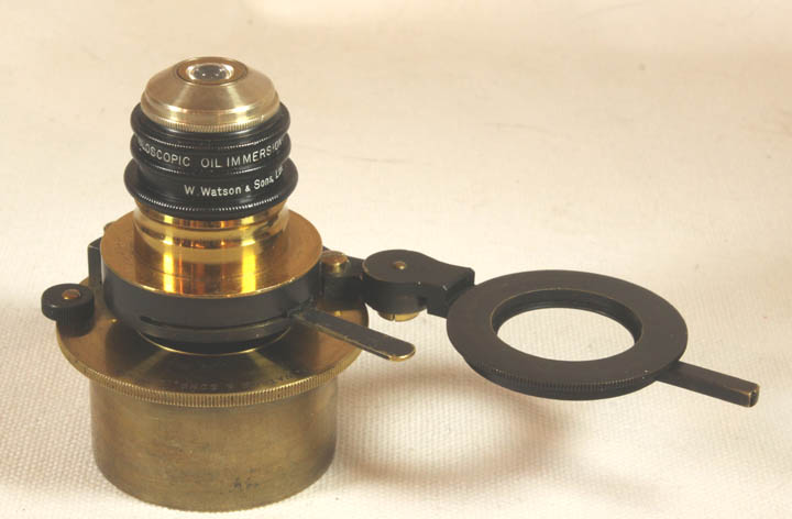 | The Watson Holos Oil Immersion Condenser with a n.a. of 1.0 dry and 1.35 oiled, was manufactured starting about 1898-9. |
| c.1901- | Watson Universal Condenser | 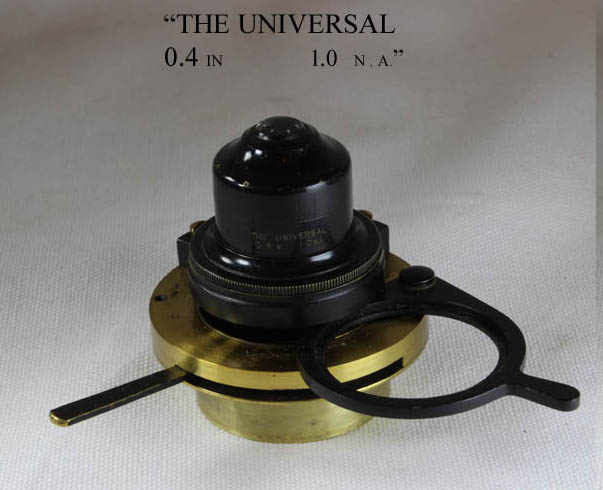 | The Watson Universal Condenser was first reported in the JRMS of 1901. Its large diameter made it very suitable, with the top element removed, for lower powers. It came with a filter/stop holder under the optics and an iris diaphragm beneath that. |
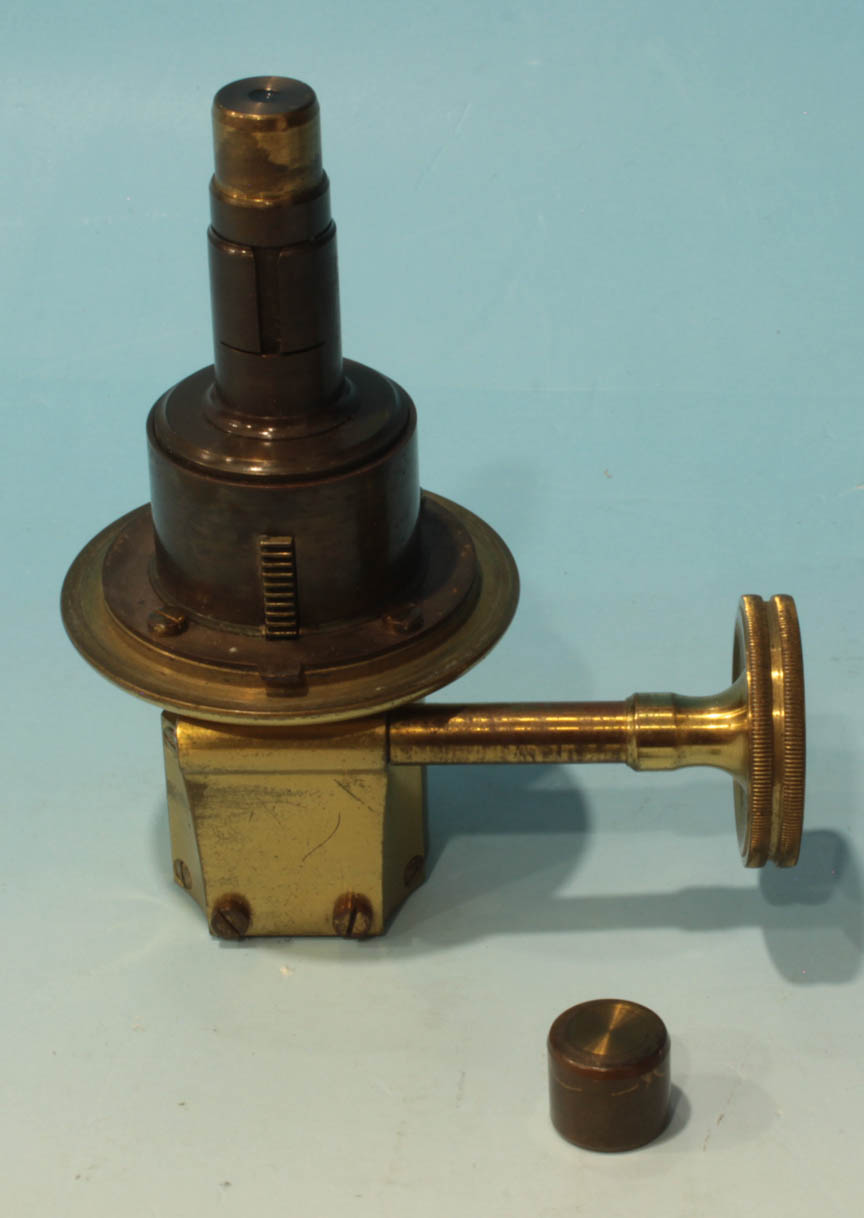
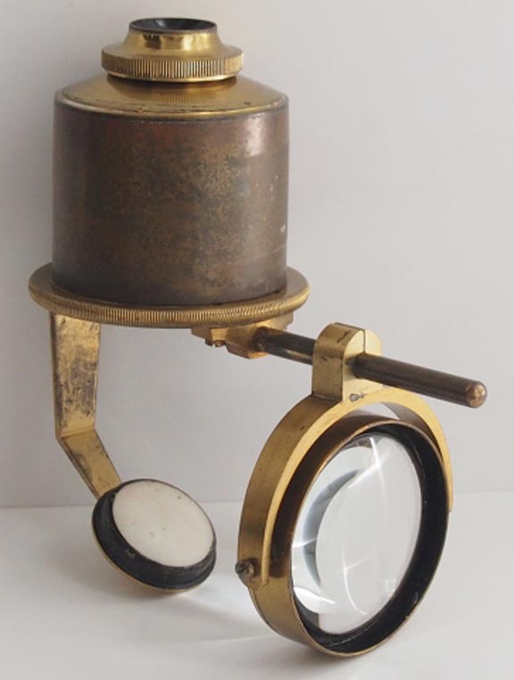
| c. 1902- | Watson Macroilluminator for Low Power Illumination | 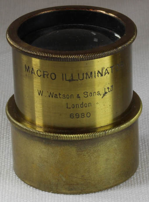 | This condenser was developed to provide uniform illumination of a large specimen viewed under low power objectives, especially for photography. |
| c. | XXXX |  | XXXX |
| c. | XXXX | | XXXX |
| c. | XXXX | | XXXX |
| c. | XXXX | | XXXX |
| c. | XXXX | | XXXX |
| c. | XXXX | | XXXX |
| c. | XXXX | | XXXX |
| c. | XXXX | | XXXX |
| c. | XXXX | | XXXX |
| c. | XXXX | | XXXX |
| c. | XXXX | | XXXX |
| c. | XXXX | | XXXX |
| c. | XXXX | | XXXX |
| c. | XXXX | | XXXX |
| c. | XXXX | | XXXX |
| c. | XXXX | | XXXX |
| c. | XXXX | | XXXX |