Back Button

MICROSCOPE-ANTIQUES.COM     © 2013-19.


HARDNESS TESTER FOR USE WITH MICROSCOPE

MAKER: SPENCER

DATES of PRODUCTION: 1920's to 1950's(?)

SIGNED:'MICROCHARACTER, American Optical Co, Buffalo 15, N.Y., Made in U.S.A.'

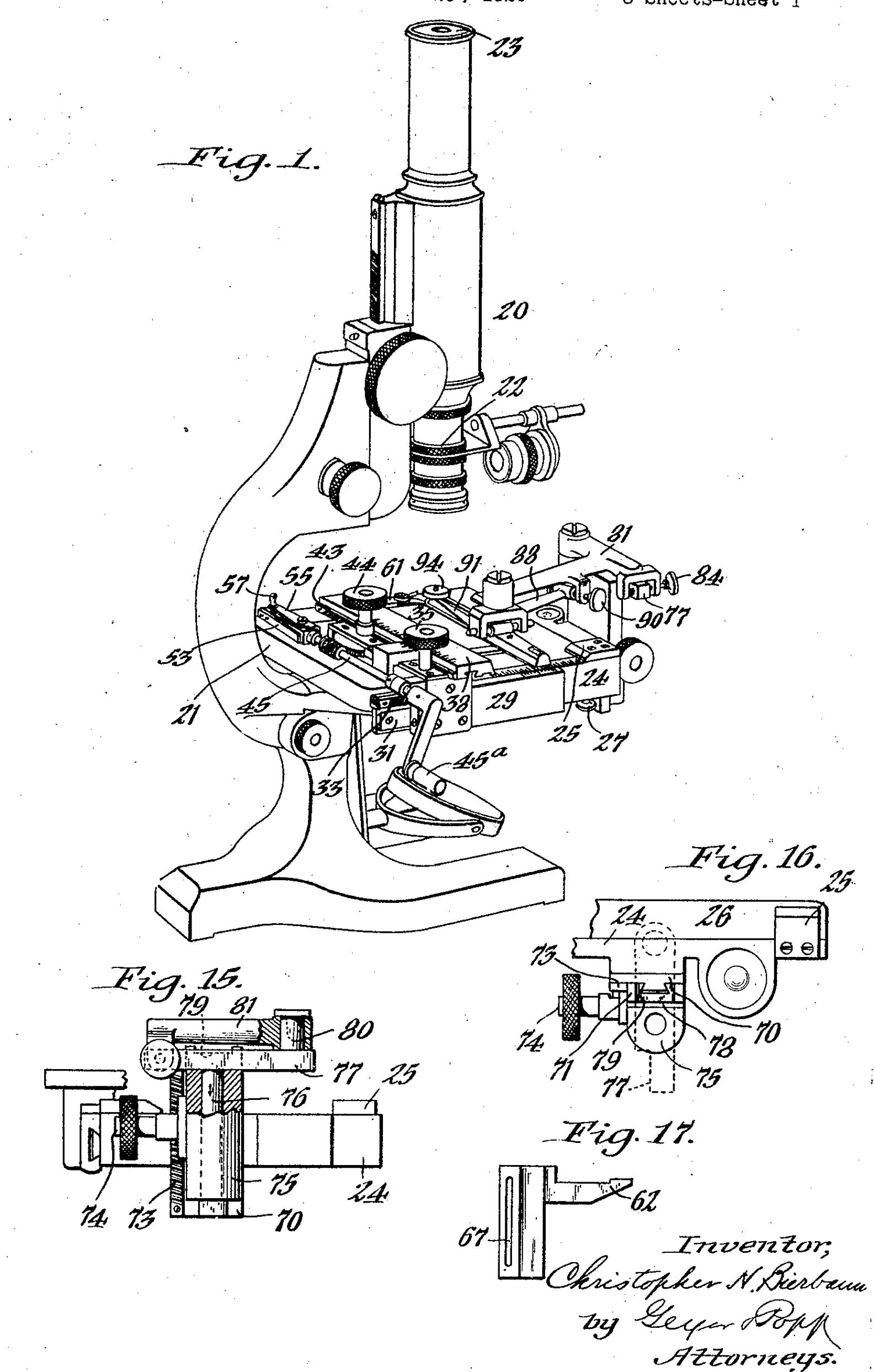
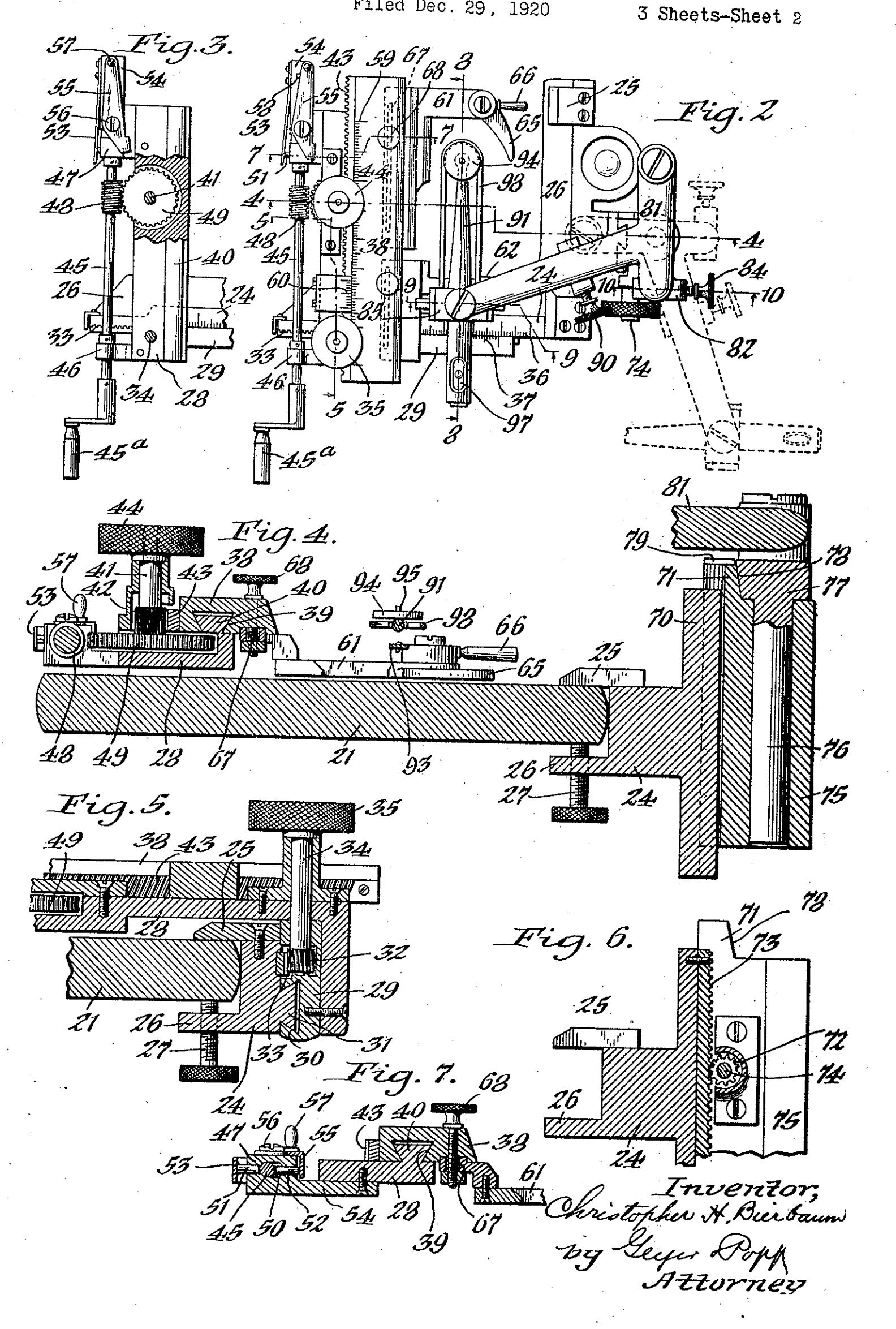
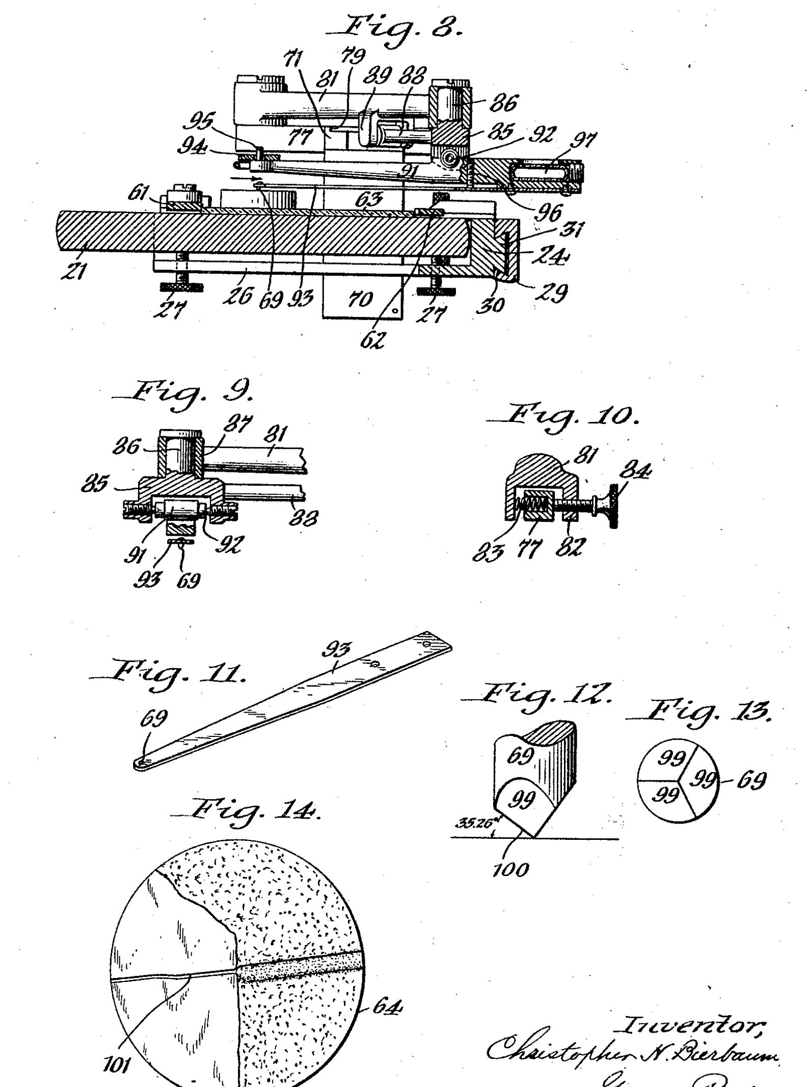
This page shows images of the Microcharacter device from the patent papers along with a simple key list to the numbers. Note that some parts are mis-numbered in the drawings.

Microscope Microscope Microscope


KEY TO FIGURES OF THE PATENT FOR THE MICROCHARACTER:
-20 microscope
-21 microscope stage
-22 vertical illuminator
-23 ocular micrometer
-24 stationary horizontal frame of microcharacter (L-shaped) [NOTE: in the second drawing 24 is erroneously used to label a different part.]
-25 Top jaw formed by clamps to hold microcharacter on stage
-26 Bottom jaw ditto
-27 clamping screws
-28 Primary slide
-29 carrying bar on end of primary slide
-30 Dovetail groove on inner surface of transverse bar
-31 Tenon fitting into 30
-32 Pinion actuating slide 29 and meshing with
-33 Rack fastened to the outer side of frame 24(not on mine)on mine fastened to the outer side of primary slide 28
-34 spindle
-35 knob to operate pinion 32
-36 scale on slide bar
-37 vernier on outer frame
-38 secondary slide mounted on end of the primary fitted with a dovetail groove on its inner (not bottom) side
-39 dovetail groove in 38
-40 dovetail tenon arranged on the outer side of the frame side (not slide)
-41 Rapid feed(horizontal) spindle carrying pinion 42
-42 pinion for horizontal motion
-43 rack on the outer side of the secondary slide 38
-44 knob for pinion 42
-45 shaft of the slow feeding horizontal device
-46 front bearing of shaft; this bearing is encased in moveable casing allowing the shaft to move outward when disengaged from the worm wheel
-47 rear bearing with elongated opening 50
-48 worm engages the worm wheel 49 secured to the spindle of 41
-49 Wormwheel on spindle 41
-50 Horizontally elongated opening with spring tension on shaft 45 via a pin
-51 and 52 pins
-53 spring acting against the pin abutting the shaft 45
-54 bracket carrying spring
-55 Shipper lever which when pushed towards the device holds the spindle away from worm wheel; a pin protruding up serves to hold it in place; to disengage and allow the spring to return the spindle worm to the worm wheel, the lever is simply lifted up slightly to clear this pin 58
-56 fulcrum of shipper lever which holds the spindle away from the wheel
-57 knob controlling 56
-58 locking pin or stud to hold the shipper lever in position for disengaging worm.
-59 scale for secondary slide
-60 vernier for secondary slide (not part of my model)
-61,62 Jaws of the slide holder which on one end has a pivoted sprung finger lever
-63 slide of subject
-64 sample on slide
-65 pivoted sprung finger
-66 handle for 65
-67 slot for jaws
-68 clamping screw for jaws
-69 stylus point cutter
-70 Standard, carrying a vertically adjustable slide projecting from the front of the main frame
-71 Vertically adjustable slide to hold the
-72 Pinion adjusting the vertical slide by rack
-73 Vertical rack
-74 shaft for pinion
-75 upright sleeve to receive T-head spindle
-76 spindle holding T-head
-77 T-head
-78 stop face to maintain position of T head parallel to secondary slide, 38
-79 locking recess which the T-head locks into after being lifted up and turned 1/4 turn counterclockwise
-80 Upright stud on which allows pivoting of horizontal bracket 81, also T-shaped
-81 Horizontally adjustable bracket which carries the mounting for the cutting point
-82 Yoke which receives the adjacent end of T head 77 -83 Spring in Yoke
-84 Adjustment knob acting on yoke for lateral adjustment of the cross bar of bracket 81
-85 yoke on end of bracket 81 with upright stud (86) with bearing 87
-88 Laterally extending arm on yoke 85, adjustible in horizontal plane
-89 Yoke on lateral arm 88 with adjusting screw
-90 adjusting screw and spring
-91 Vertically swinging beam suspended slightly above its center of gravity in the yoke 85 with saphire jewels
-92 Saphire jewels for beam 91 fulcrum
-93 Delicate spring on which the free end has the cutting point mounted
-94 small weights which are placed on stud
-95 stud for weights at front end of beam 91 directly over the cutting point
-96 tension adjuster for spring 93
-97 Spirit level carried on rear arm of the beam 91 to adjust jewel-spring 93
-98 Guard to protect the jewel point
-99 three facets of cutting point