MICROSCOPE-ANTIQUES.COM © 2013-26.
AYLWARD SELF-CENTERING SLIDE-RINGING TURNTABLE
Model: THE CONCENTRIC
c. 1881-1891
Author: Barry Sobel
Editor: Joseph Zeligs
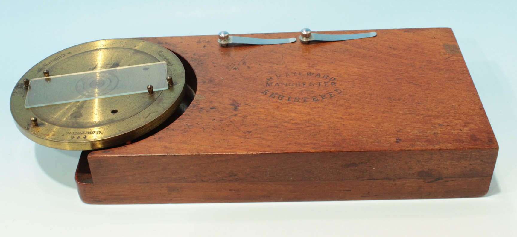
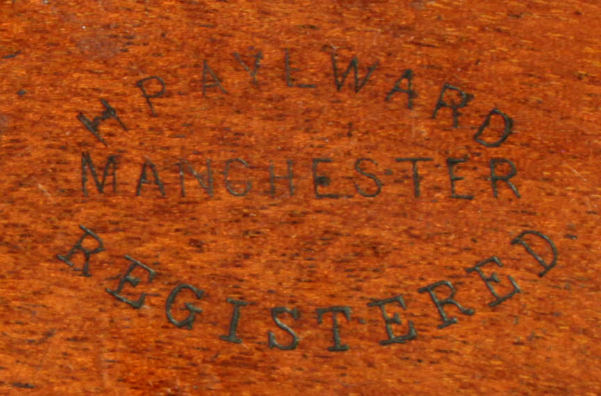
 Signed on the wooden support block in an oval pattern:
 H.P. AYLWARD, MANCHESTER, REGISTERED
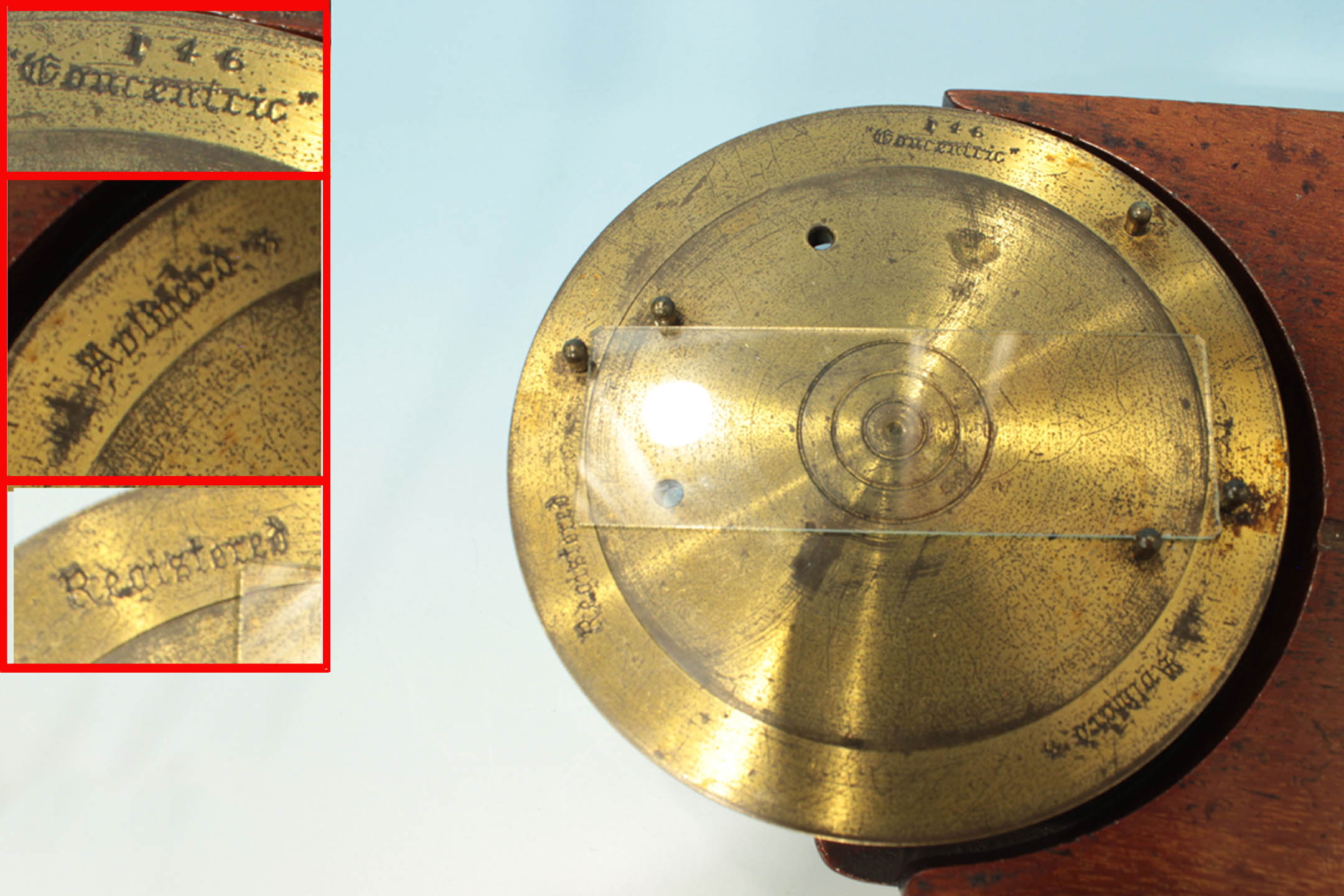
, and around the outer ring of the brass turning part:
146,Concentric
...H.F.Aylward ...Registered
.
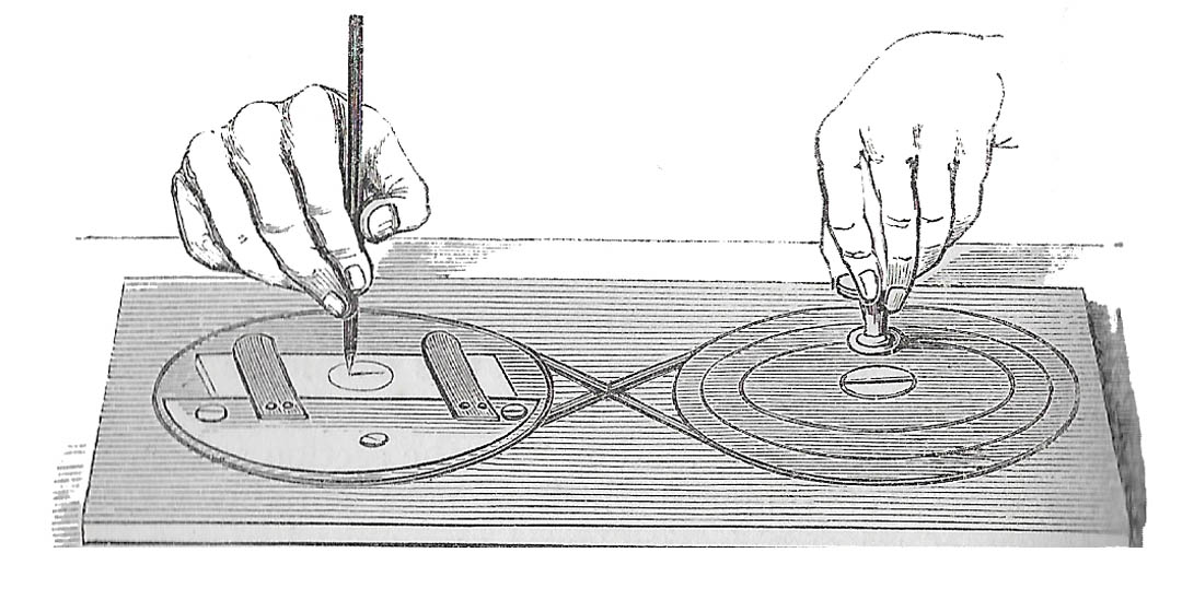
In use, the brass table is spinning. The user would employ a pointed paint brush, usually hand-held, to apply cement and/or sealant while the device was spinning. After the specimen is secured under the coverslip the table is used to to coat the edge of the coverslip with a sealant ringing compound such as asphaltum, or colored thick lacquer. These compounds are quite thick and so do not fly off due to the momentum of the spinning table. Occasional devices like this had a holder for the brush, but most depend on a the user's wrist being steadied on the stationary surface of the device. A video of this technique is shown here using a modern turntable(without an automatically centering mechanism). These turntables were also used for cutting small circles in thin glass(coverslips) with a diamond-tipped pencil, drawing smaller circles on a coverslip to draw attention to an area of interest, and, by building up several layers of sealant, producing a shallow cell
. Deep cells were usually made with a metal or glass cylinder cemented to the slide; these deeper cells still required sealant around the coverslip.
SLIDE CENTERING MECHANISM: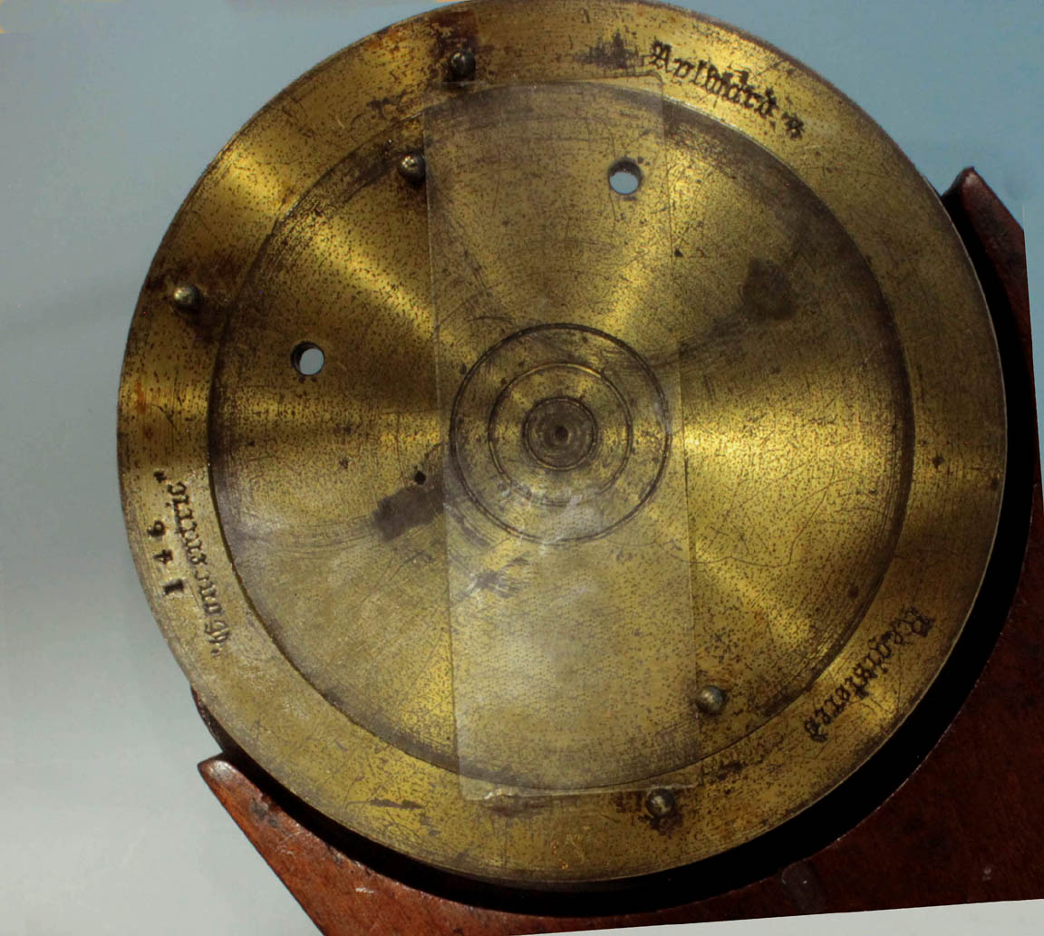
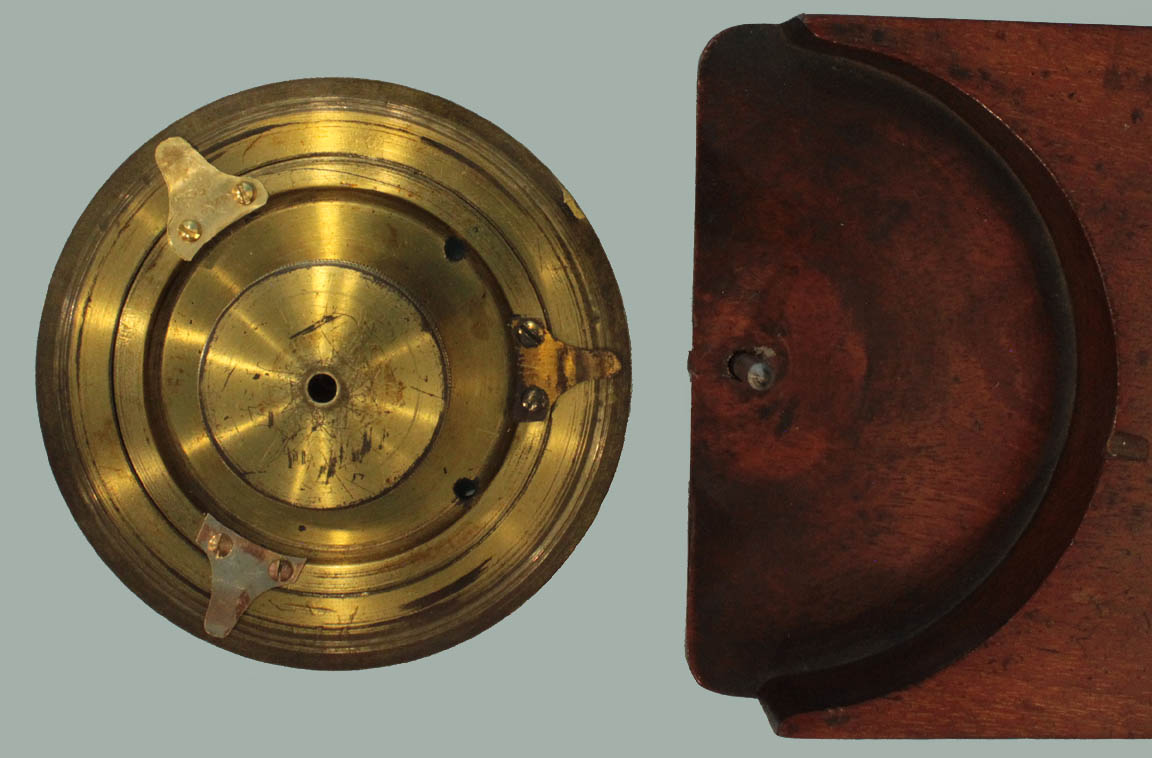
Before applying the ringing, the center point for the ringing on the slide must be positioned at the center of the rotatable brass table. If the center for the ringing is a known point on the slide, this point can be manually aligned to the center of the table, using the concentric markings on the table, and then fixing the slide in position with the two stage clips provided, as illustrated in the video, linked above. These stage clips are stored as shown in the top illustration, when not in use.
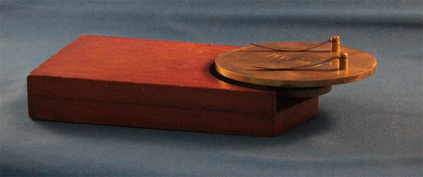
If it is desired to center the ringing at the geometric center of the slide, then the self-centering mechanism supplied with the Aylward device described on this page is to be utilized. As shown in the image to the left, this mechanism consists of two concentric, independently-rotatable, plates, with pairs of posts on opposite sides of each plate, equidistant from the center, to hold the sides of the slide. The inner plate fits over a pointed steel axle and is joined with the outer plate by three leaf springs underneath, as shown in the image to the right. The narrow portion of the slide is placed between the posts on the inner plate and the long portion of the slide between the posts on the outer plate. The outer plate is then rotated clockwise and the inner plate counterclockwise, until all four sides of the slide are in contact with the posts. Click on the image to the left for an illustration of how this mechanism works. Note that the mechanism works well for slides of various widths, but it is designed for slides close to the standard three-inch length. H.P. Aylward reported the Concentric Turntable on page 851 of the JRMS in 1881.
HISTORY AND USAGE OF SLIDE RINGING TURNTABLES:
 Slide-ringing tables, also known as
 whirling tables
and cell-making instruments
, were used to simplify the application of a sealant or glue in a nice circular pattern on a slide. They were very useful in building up layers of shellac or similar material to form shallow cells or toring the top of metal or glass cells glued to the slide for careful application of a coverslip. One of the oldest designs, dating to no later than the 1850's made use of two disks-one holding the slide driven by another disk turned by a crank with the two disks connected by a cord.
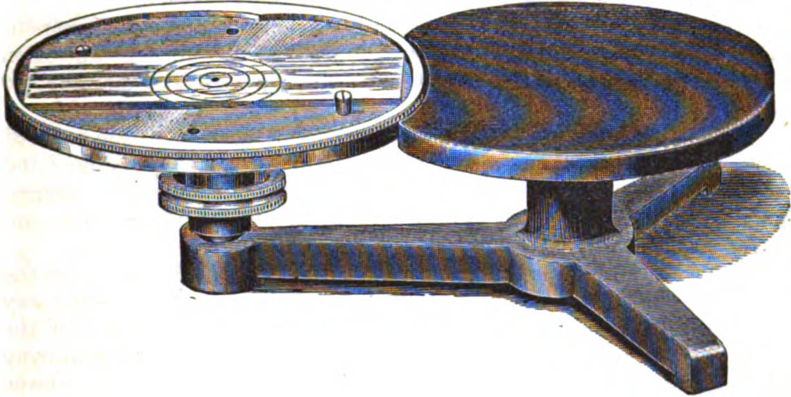
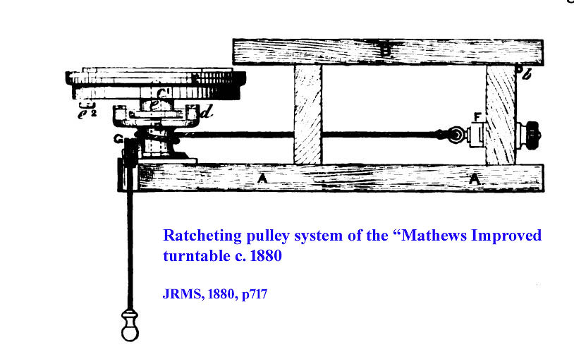 Soon the turntables were made of brass, supported by wood or metal bases. They could be rotated slowly by directly rotating the wide, slide-holding disk with one's finger, or more rapidly by using a smaller diameter knurled knob located under the larger slide-holding turntable. There were even some that had a cranking mechanism with a pulley system, or, as shown here to the right, even a ratcheting pulley system acting on the axis of rotation allowing rapid rotation, somewhat like the starting mechanism for a gas-powered lawnmower.
 The simplest models, known as the Shadbolt type, consisted of just a round brass table with concentric rings engraved on the center, supported on a simple wooden base. The base supported the brass table on metal rod with a point to minimize friction. The user would simply manually align the point on the slide which is desired to be the center of the ringing, with the center of the brass table, using the concentric circles on the table, and then fixing the slide in place with the stage clips provided, followed by spinning the table while applying the cement or sealant. The supporting base of these was often a piece of hardwood, though later models had metal bases or supports. These devices were not only supplied individually, but also as part of complete slide mounting outfits. Such an example, included in Collins' Slide Mounting Outfit, is shown here.
 In these outfits, the base was often smaller than the stand-alone types so that the device would fit conventiently into the cases. In the instance of the
Universal Dissecting & Mounting Microscope Kit,
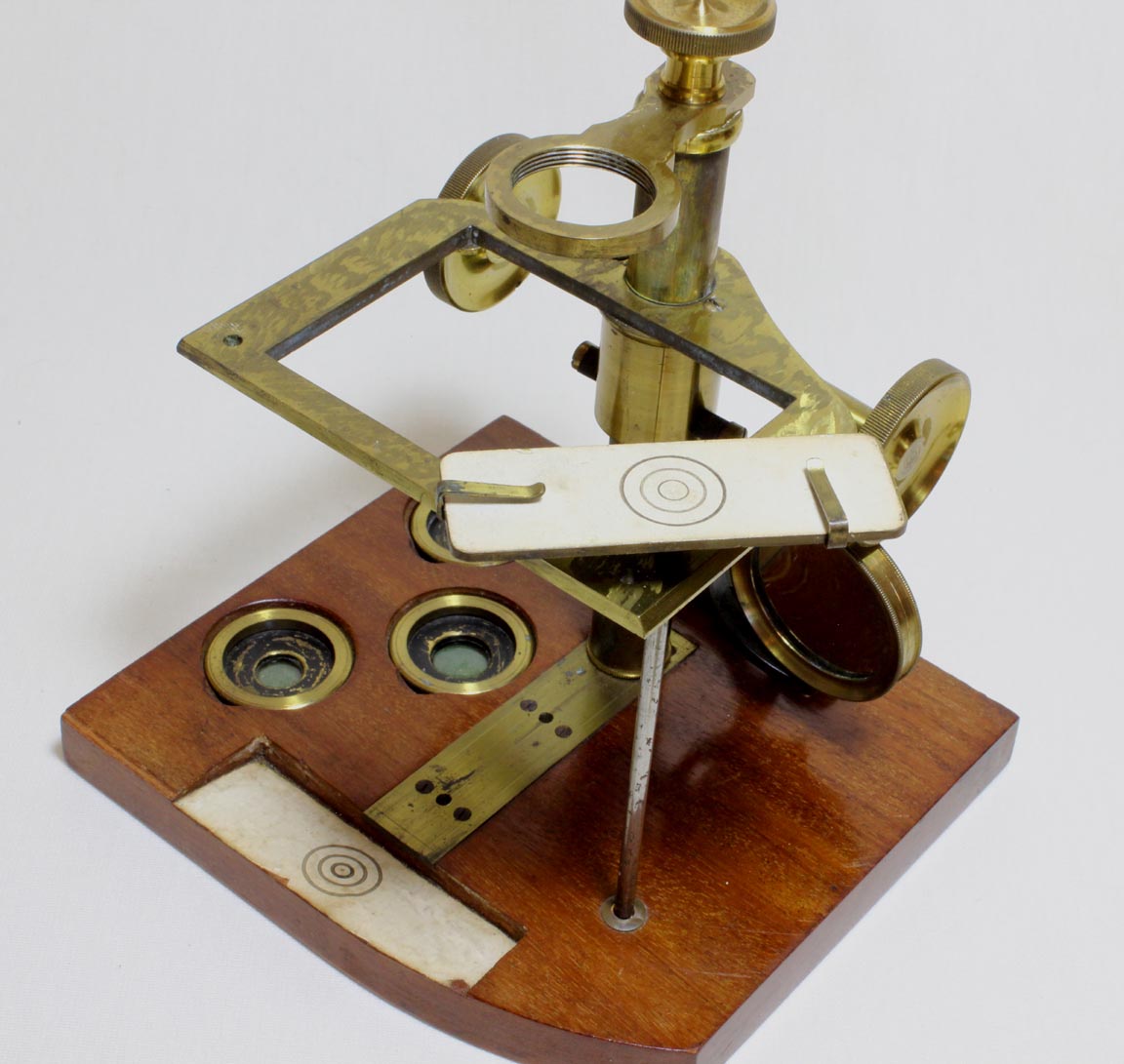
sold by Field & Son in the 1870's, the turntable, instead of being round and large, was rectangular and only slightly larger than a standard slide. The turntable had a rod fastened to the center of its bottom. This rod fit through a hole in the stage of the included microscope. The bottom of the rod tapered in a cone shape and rests on a ferrule on the wooden foot of the microscope. This enabled it to spin quite nicely.
 Stand-alone ringing turntables of brass were often supplied with cast iron bases. Shown to the right is an example by the McIntosh Battery & Optical Company (Lyman McIntosh). The smaller diameter knurled brass knob under the slide support is attached to the same axle as the main turntable on top. Its smaller diameter facilitates spinning the table more rapidly than by directly using one's finger on the edge of the top turntable plate. This type of turntable made of brass supported by a cast iron base, was the most common type made. Examples signed by both British and American makers are well known and include those by Bausch & Lomb, Queen, Watson, Beck, Baker and many others. Most are quite similar to the one shown here, with only minor variations. This type of ringing table is still made today and a current version is available from Brunel Microscopes in England.
Although a rough centering can be easily accomplished manually by placing the slide over the engraved rings on the turntable, replacing ringing cement in the exact same location is not easily done manually, especially if the slide has been removed from the turntable to dry and needs further work. For this reason, various types of modifications were invented to allow the slide to be centered to the same location over and over again. Among the most sophisticated were self-centering
turntables. These devices were designed to reproducibly center to the same location, thus facilitating reapplying ringing compound at a later date, or effecting a repair.
One such device was designed by Walter Bulloch. He called it his Turntable for Microscope Slides
. It was offered by the Boston Optical works as early as 1873, though it was patented on April 20, 1880. This device uses a Archimedian spiral* mechanism to automatically center the slide as the knob is turned.
 Another, centering type of turntable, but with a different mechanism, was sold and patented by Sidle with the Model name of
 THE CONGRESS
. The patent for Sidle's Congress Turntable was issued on November 30, 1880, only about 7 months after Bulloch patented his turntable. Sidle's device, like Bulloch's, moved two L-shaped slide holders at the same time to center the slide, but instead of these being carried in slots, they ride on two brass disks rotated simultaneously by the control knob; as one moves clockwise, and the other counterclockwise, they move either closer to or further away from the center of the table to center the slide between them. This version used two complementary gears to adjust the centering of the pieces holding the slide. Although it works smoothly, the Sidle version has one small disadvantage over Bulloch's: because the L-shaped pieces are moved closer or further apart by rotating on disks, the direction the L-shaped piece is facing changes as the disks are rotated. As a consequence, they will not automatically properly orient themselves to the slide being used and will need some re-alignment until they are close to the edges of the slide. In Bulloch's arrangement, because the pieces ride in a straight line, once set in the direction they need to be in, this does not change as they are moved towards the slide. In addition, Bulloch engraved the table to show where the slide would be so the direction of these pieces can be set before one begins to move them.
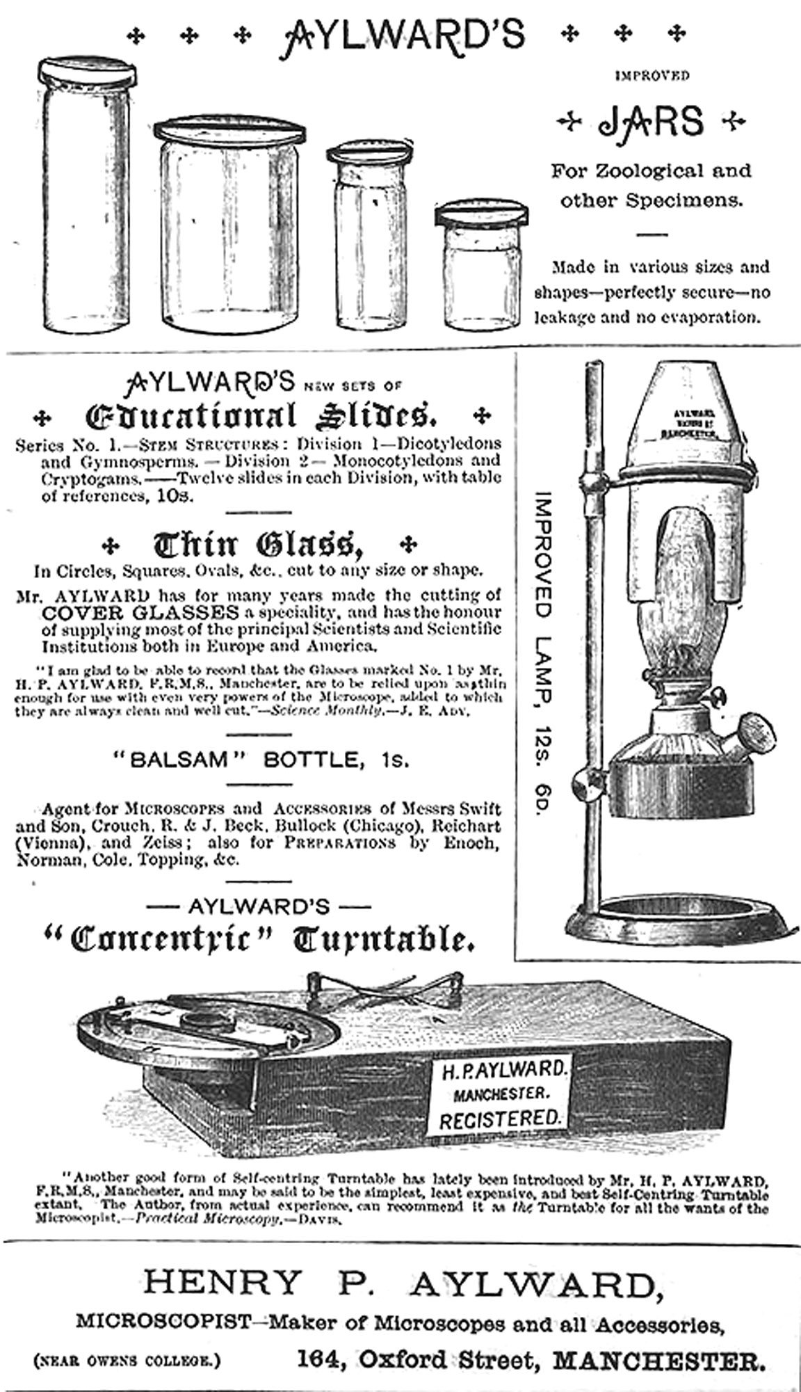
Aylward's Self-centering Turntable was introduced no later than 1881, as noted in The Northern Microscopist-Volume 1, page 183. An ad from 1888 is shown to the left. It continued to be advertised and noted in Journals and Books through at least 1891.
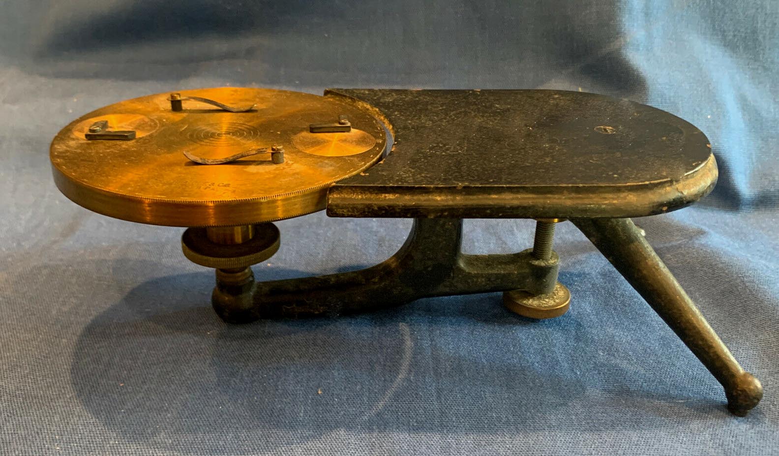
In 1884 Zentmayer reported his version of self-centering turntable in the JRMS p 475. This turntable has two pins on an inner disk, each pin equidistant from the center, and at opposite sides of the turntable. When a slide is made to contact the two pins, one on each side of the slide, the slide is centered in the short axis. To center it in the long axis, the outer ring, which has an oval-shaped inner lip, is turned with the inner disk and slide held steady, and the oval-shaped raised inner edge centers the slide as opposite sides of the oval contact opposite corners of the slide.
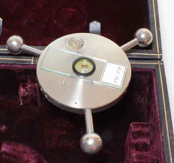
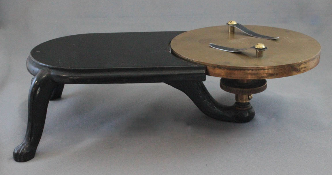
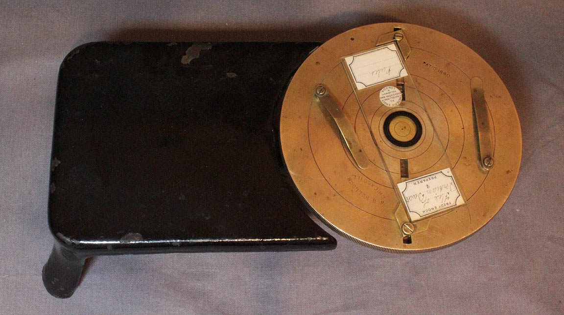
In my own opinion, the best automatic centering mechanism for a ringing table was the one developed by Ezra Griffith which automatically centers the slide with a sprung centering mechanism that is much easier to use. It is featured as part of the removeable foot of the Griffith Club microscope, and was also sold as a stand-alone unit with a black painted cast iron support similar to the support shown, for example, on the Bulloch model above. In use, the example used as part of the foot of the Club microscope, the foot is removed from the microscope, turned over and placed on a pointed rod inside the case. The three ball feet act to add weight to the device to maintain its momentum during rotation. Illustrations of how the mechanism is used can be accessed by clicking on the image to the right. Ezra Griffith of Fairport, New York received a patent for this device on December 14, 1886. For more about Griffith, see the History section on the page about the Griffith Club Microscope.
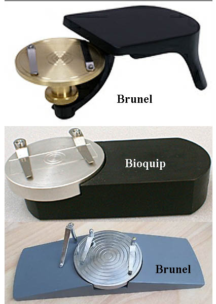
Slide ringing tables are still made today. One example is sold by Bioquip (middle image). The other two versions shown are made by Brunel. Note the design of the top one has not changed much in over 150 years. A video illustrating the use of the Brunel device is shown here.
*Although the patent refers to a volute
spiral, this is technically incorrect as a volute spiral has steadily increasing space between the coils as they move outward, whereas in this turntable, as in lathe chucks, the spacing remains constant, a form described more accurately as an Archimedean spiral. The author is grateful to Paul Ferraglio for this information.